
From local unit to central plant
When the project calls for a plant, not a unit
In any industrial or commercial project of sufficient scale there comes a point at which cooling stops being solved with distributed equipment —packaged units, mini-splits, standalone ducted systems— and starts to demand a central plant: concentrated cold-production at a single point, distributed hydraulically to the rest of the facility. The transition is not a matter of preference; it is a technical consequence.
Distributed equipment is quick to install, tolerates change and works well at small and medium scales. A central plant is justified when three conditions come into play: sustained scale, thermal continuity that admits no interruption window, and precise control of zones with different demands coexisting under the same envelope.
The ASHRAE Handbook — HVAC Systems and Equipment identifies precisely these three criteria as the thresholds that shift a project from the catalog of distributed equipment toward centralized architectures. That is the industry reading that backs the moment at which the plant stops being one option among several and becomes the only technically sustainable one.
The chilled water plant: three decisions that define it
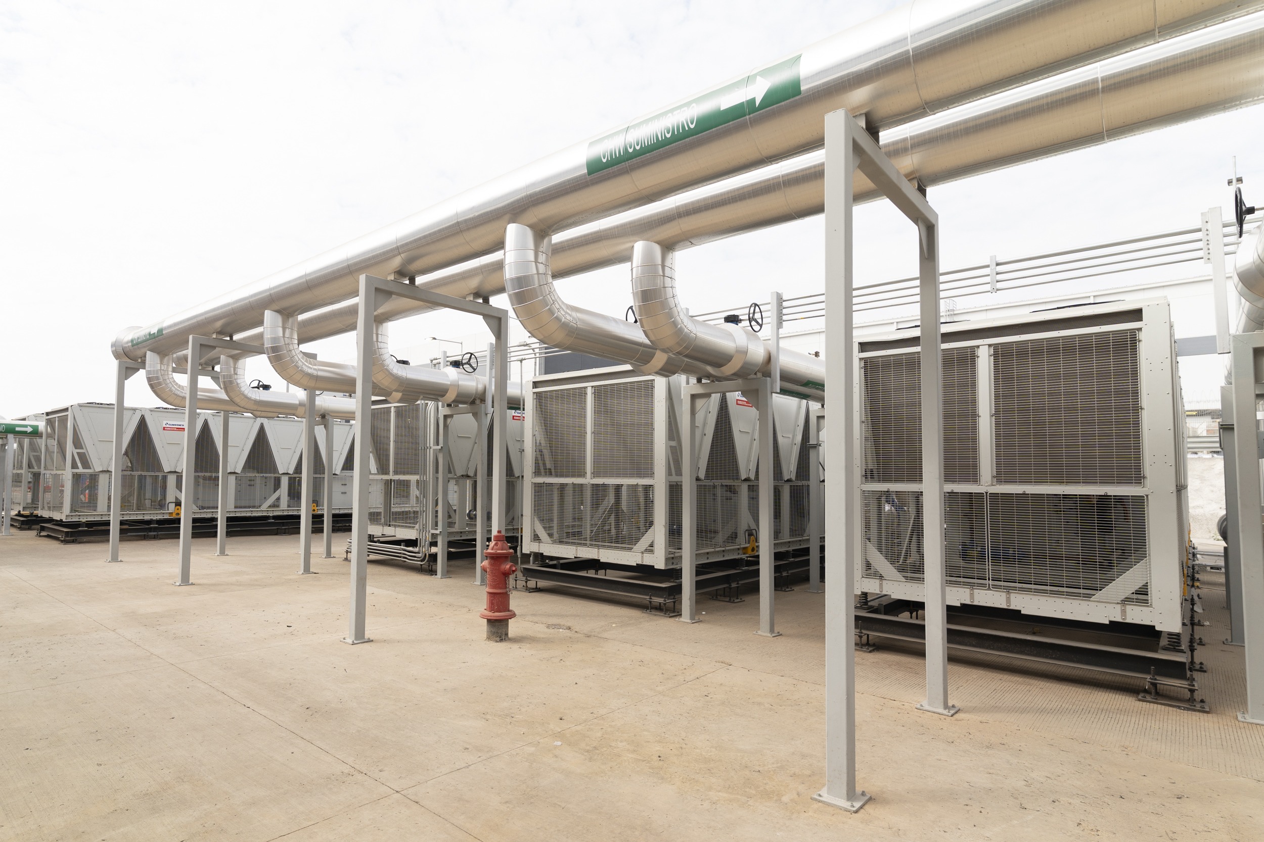
A Chilled Water Plant produces cold water in a chiller and distributes it through a hydraulic network to the units that condition process areas. The principle is simple. The three design decisions that determine whether the plant performs or disappoints are decisive.
The first is the loop architecture. A primary-secondary scheme separates the chiller loop from the distribution loop with two distinct pumping groups; a variable primary flow scheme operates with a single loop and modulating pumps. The ASHRAE Handbook — HVAC Systems and Equipment describes both as canonical options with distinct profiles of stability, efficiency and response under variable load.
The second is the heat rejection path. Where the heat extracted by the chiller ultimately goes: water-cooled towers, air-cooled condensers, or hybrid configurations. Each option has direct implications on energy efficiency —regulated by ASHRAE 90.1— and on the facility’s water consumption and physical footprint.
The third is control logic. The layer that decides when a chiller enters or exits, how it modulates against real load, how pumps respond to demand, and how the plant sustains its operating envelope through changes in occupancy, outdoor climate and internal thermal load. Here the difference between projected and real performance is played out. Reaclima’s field experience confirms a recurring principle: correcting a sizing error after commissioning is paid several times over.
Mechanical redundancy: the design that survives a single-unit failure
When the process cannot tolerate an interruption window, redundancy stops being a later addition and becomes the mechanical architecture of the plant itself. The ASHRAE Handbook — HVAC Applications and the Uptime Institute Tier classifications recognize N+1 configurations (one additional unit above the required capacity) or 2N (fully duplicated), applied not only to chillers but also to pumps, towers and the piping that connects them.
Layered on top of that architecture are the elements that make it operational: isolation valves that allow maintenance without bringing the system down, bypasses that sustain flow through transitions, and automatic switching logic that executes the transfer without human intervention. The difference between a plant with genuine redundancy and one with merely duplicated equipment lies not in the number of machines but in the hydraulic and control diagrams signed off before installation.
When thermal density outpaces air: the role of Liquid Cooling
For years, air cooling was enough for practically any computing load. That balance broke with today’s Artificial Intelligence and High-Performance Computing (HPC) workloads. When per-rack density exceeds the functional ceiling of traditional air cooling —near 20 kilowatts per rack according to ASHRAE TC 9.9— the answer stops being a larger unit and becomes a change of heat-transfer medium
Liquid Cooling is articulated in several architectures —direct-to-chip, immersion, rear-door heat exchanger— and each has specific requirements of fluid, materials and coupling with the central plant. ASHRAE TC 9.9 documents the environmental classes and thermal densities at which these architectures become necessary, and the Open Compute Project publishes open specifications for their implementation. The operational point is direct: Liquid Cooling does not replace the chilled water plant; it leans on it. Behind a liquid-cooled rack there is, in most cases, a chiller sustaining the loop. They are pieces of one system, not alternatives.
The plant as an efficiency lever
The design decisions of the plant —loop architecture, heat rejection path, control logic— have direct effect on the facility’s overall energy and water consumption indicators. In data centers, the reference indicator is PUE (Power Usage Effectiveness), defined by The Green Grid: the industry’s global average PUE holds near 1.58 according to the Uptime Institute annual report, while best-performing sites operate below 1.3. The gap is largely explained by the design of the heat rejection system and the plant’s control logic.
WUE (Water Usage Effectiveness), also defined by The Green Grid, quantifies liters of water per kilowatt-hour of computing. In regions under water stress —a growing portion of Mexican territory— the heat rejection path and water recovery technologies determine whether the site obtains permits or not. ASHRAE 90.4 (Standard for Energy Efficiency for Data Centers) formalizes both indicators as design requirements, not aspirations.
Reaclima in the field: chilled water and Liquid Cooling for a technology operation
Reaclima operates today chilled water plant services and Liquid Cooling systems with Vertiv equipment for one of the largest technology companies with manufacturing operations in Mexico. Each of the technical decisions —loop architecture, mechanical redundancy, control logic— is executed there under the requirement of continuous operation. It is the terrain where design becomes verifiable performance, and the operational learning it generates feeds back into every new project the team takes on.
Reaclima criterion for hospital: chilled water plus control system
In hospital installations, general HVAC standards admit different technical solutions. ANSI/ASHRAE/ASHE 170 sets ventilation and pressure differential requirements; the ASHRAE Handbook — HVAC Applications recognizes chilled water systems, direct expansion systems and VRV as technically viable options for different types of health care facilities. The regulatory framework does not impose a single technology: the reading that matters here is operational, not one of compliance.
Reaclima’s field experience in hospital installations has led to a consistent recommendation: for the thermal multi-load of a hospital —administrative areas, clinical areas, operating rooms and critical spaces coexisting under the same envelope— the first option is a chilled water plant integrated with a centralized control system. The reason is operational behavior. The plant with centralized control responds with greater predictability to the thermal variability of the building throughout the day, tolerates occupancy peaks better and offers a more orderly maintenance path. It is a Reaclima criterion based on accumulated operation, not a rule of the standard.
A technical partner for the project that calls for a central plant
When a project calls for a central plant —by scale, by continuity, by criticality— the difference between a plant that sustains the operation and one that limits it is decided at the design stage. Loop architecture, mechanical redundancy, control logic, correct sizing, execution discipline. Each of these decisions has consequences that operate 24/7 throughout the useful life of the installation.
Reaclima operates this class of projects with technical teams deployed at large-scale technology installations and with a track record in the hospital, pharmaceutical and industrial manufacturing sectors. If your next installation requires a scale chilled water plant, Liquid Cooling systems articulated with it, or the engineering that both decisions demand, let’s talk..


