
Operation and Maintenance of Liquid Cooling Systems: Operational Continuity in Mission-Critical Data Centers
Introduction: Commissioning is the start, not the finish
The commissioning of a liquid cooling system —which we closed in the previous installment of this cycle— is not an arrival point. It is the moment when the longer question begins: how the facility's performance is sustained across the 15 to 20 years of its operational life.
ASHRAE Technical Committee 9.9 released a technical bulletin in February 2026 on the resiliency of liquid cooling systems, warning that "the loss of cooling can be catastrophic when extreme thermal loads are involved" (ASHRAE TC 9.9, 2026). The warning is not rhetorical: in racks with densities of 80 to 120 kW, a loss of coolant circulation drives processors to thermal shutdown in under three minutes, and the damage to semiconductor components from overheating can be permanent.
The initial investment in a liquid cooling system for a hyperscale data center is in the multi-million-dollar range and varies with installed capacity, thermal density, and redundancy level. What pays back that investment —low PUE, high rack density, reduced operating costs— is not earned on startup day: it is earned every day of the system's service life.
Reaclima has participated in mission-critical HVAC projects such as Foxconn GDL Vesta 8 and Amazon AWS Querétaro, where the availability standard exceeds 99.99% annually —a maximum margin of 52.6 minutes of downtime per year—. This article gathers the operation and maintenance principles that sustain that standard.
Continuous monitoring: what the BMS must see at all times
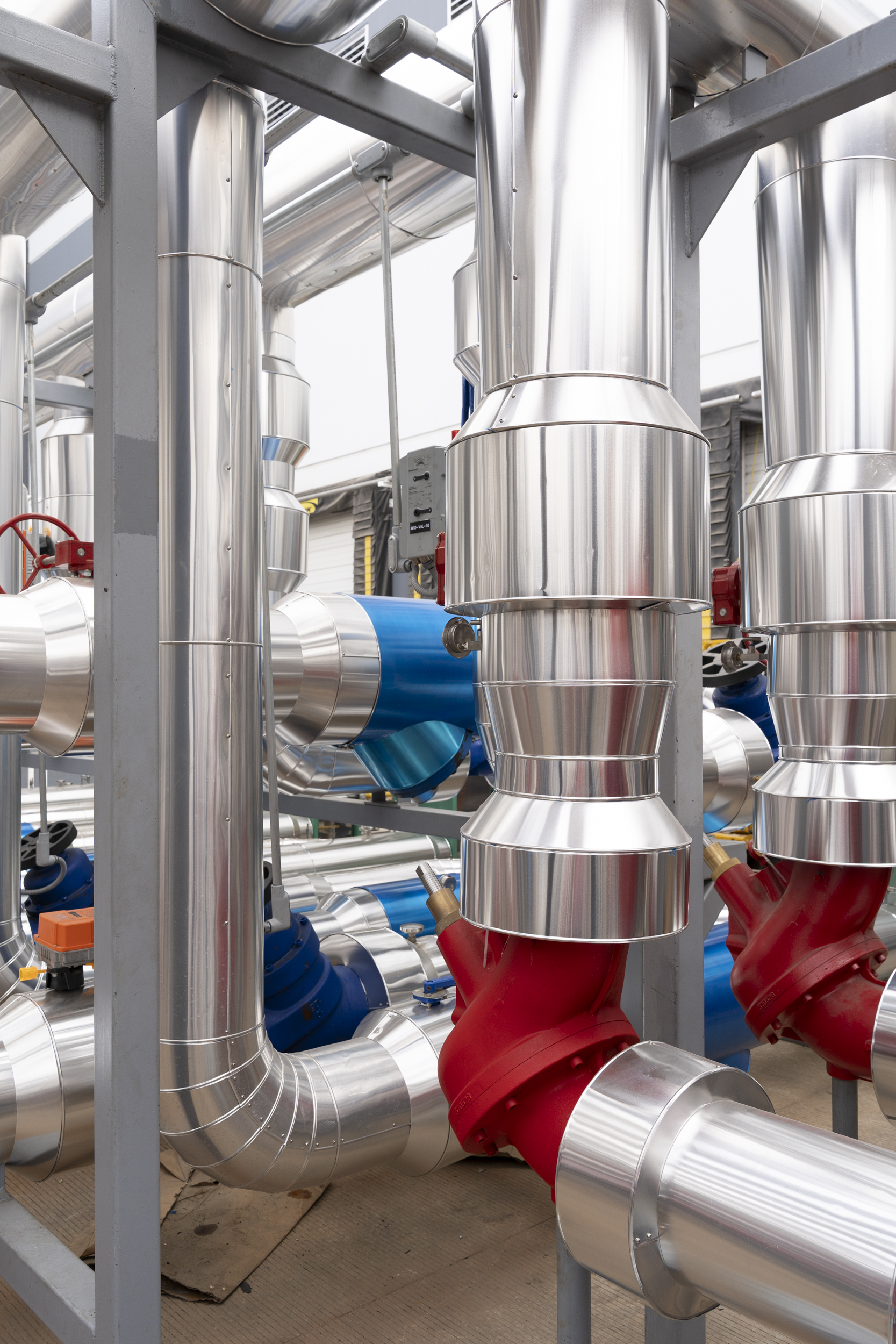
Modern systems integrate distributed instrumentation feeding into BMS (Building Management System) or DCIM (Data Center Infrastructure Management) platforms. The role of monitoring is not decorative: it is to catch deviation while it is still small, before it escalates into an incident.
Thermal domain
Coolant supply temperature operates, depending on the technology, in a range of 18 to 30 °C. The warning alarm is set at ±2 °C from the design setpoint, and the critical alarm at 35 °C —the threshold associated with the onset of thermal throttling in processors—. When this temperature climbs in a sustained manner, what usually sits behind it is fouling in chiller condensers, insufficient heat rejection at the cooling tower, or a clogged filter in one of the heat exchangers.
The Delta T between return and supply lives between 8 and 15 °C depending on configuration. The extremes are what matter here: a Delta T below 5 °C points to flow bypass or excess flow rate, while a Delta T above 20 °C reveals insufficient flow and opens the door to localized hot spots on the components generating the most heat. A 20% deviation from design value is reason enough to trigger an alarm.
Processor junction temperature is read directly via IPMI, Redfish, or proprietary protocols. On Xeon Scalable, EPYC, or NVIDIA H100 platforms, internal sensors allow two thresholds to be configured: warning at 75 °C (when throttling begins) and critical at 95 °C (10 °C below the hardware shutdown point).
Hydraulic domain
Volumetric flow is measured at the points where its variation has consequences: CDU outlets, rack manifold inlets, and exchanger returns. Standard instrumentation includes non-intrusive ultrasonic, turbine, and electromagnetic flow meters. A 10% drop against design value triggers an alarm; below 70%, the alarm is critical. The most frequent cause of gradual flow loss is a clogged filter. Pump impeller wear follows, and over time, deposits on cold plates from degraded glycol precipitation or biological growth.
Differential pressure is the other primary hydraulic indicator. It is monitored at filters, exchangers, cold plates, and manifolds. When it rises 25% above the initial value, progressive obstruction is underway. Above 2 bar, the risk is no longer about efficiency: it is about mechanical damage or bypass. For 5 to 10 micron filters, replacement should be scheduled when differential pressure reaches the 1.0 to 1.5 bar range —before the system starts to suffer from it—.
Coolant quality
Verification frequency matters here as much as the data itself. Propylene glycol (or ethylene glycol per specification) concentration must remain between 30% and 50%. It is checked quarterly under normal operation, and monthly when there are frequent top-offs or suspected leaks. Dilution from make-up water raises the freezing point and weakens corrosion protection; going above 60%, on the other hand, makes the fluid more viscous and less efficient at transferring heat.
pH is held in a slightly alkaline range, between 8.0 and 9.0, to minimize corrosion. Electrical conductivity must stay below 10 µS/cm in deionized water and below 500 µS/cm in treated water. Monthly verification is sufficient. If pH drops below 7, corrosion inhibitors are depleted or metallic products have dissolved into the fluid. If conductivity rises, a contaminant has entered or metal is dissolving somewhere in the loop.
The turbidity target is below 10 NTU, with a particle count above 10 microns below 1,000 per 100 ml. When these indicators move, the cause is almost always one of four: pump seal wear, internal corrosion, biological growth, or insufficient filtration.
Preventive maintenance: the daily discipline that prevents the incident
Preventive maintenance is the way of paying small known bills instead of one large unknown bill. The usual structure follows a tiered frequency according to the component and the criticality of what it watches over.
Daily, operations staff walks CDUs and pumps for visual inspection —leaks, abnormal noise, vibration—, reviews active alarms in the BMS/DCIM, checks levels in expansion tanks, and pays close attention to rack manifolds.
Weekly, filter differential pressure is logged in the maintenance record, absorbent paper is run across critical quick-disconnects, the operation of automatic air vents is verified, and the temperature history of IT components is reviewed to catch gradual trends that go unnoticed day to day.
Monthly inspections open the analytical front: pH, conductivity, glycol, and turbidity of the coolant; thermography on the electrical connections of pumps, VFDs, and CDUs; sensor cross-check against calibrated reference thermometers; and cleaning of the air filters on CDU fans, which dust keeps clogging without anyone noticing.
Each quarter, samples should be sent to an external laboratory for extended analysis —dissolved metals, microbial count, residual inhibitors—, fouling in heat exchangers should be assessed, control valve response should be tested, and the condition of thermal insulation should be reviewed.
Semi-annual inspections are more invasive: opening and internal inspection of CDUs (with chemical cleaning if efficiency has degraded by more than 10%), scheduled replacement of filter cartridges, examination of pump mechanical seals and, above all, N+1 redundancy testing through failure simulation. If it has never been verified that the redundant system actually takes the load, the first time should not be during a real incident.
Annually, the major work is due: full drain and chemical cleaning of the system with citric acid or trisodium phosphate; replacement of the refrigerant fluid —every 3 to 5 years per analysis, or sooner if degradation is clear—; recalibration of critical instrumentation at an ISO 17025-accredited lab; and the hydrostatic pressure test at 1.5× operating pressure for four hours, which closes the annual validation cycle.
Incident management: three scenarios trained before they happen
No preventive program eliminates the possibility of failure. What a mature operation does is rehearse the responses before they are needed.
Primary pump failure. Detection usually arrives simultaneously through three channels: low-flow alarm at the affected manifold, rising return temperature, and differential pressure alarm at the exchanger. Under N+1 redundancy, the automatic response activates the standby pump, raises speed on the remaining pumps to compensate, and notifies personnel via SMS or email. The human part comes next: isolating the failed pump with ball valves, opening it to inspect mechanical seal, impeller, and bearings, replacing what is damaged, and returning it to service only after partial-load testing.
Leak at a server quick-disconnect. Detection here may be instrumental —humidity sensor in the manifold, turbidity that suddenly rises in the fluid— or visual, when a technician spots it in passing. The immediate response isolates the server with the manifold valves; if the environment is virtualized, VMs are migrated to servers with operational cooling. Corrective actions almost always run the same course: inspect and replace O-rings, apply the torque specified by the manufacturer, clean sealing surfaces with isopropyl alcohol, and verify for 30 minutes that the reconnection does not weep.
Efficiency degradation in a chiller. This one does not announce itself with a single alarm. It shows up as a pattern: supply temperature creeps up, Delta T at the CDU exchanger drops, chiller electrical draw climbs without a thermal load increase to justify it. Diagnosis reviews pressure and temperature in the compression circuit, checks for fouling in the condenser, verifies that cooling tower fans are working properly, and compares current kW/ton against design value. Standard corrective actions: chemical cleaning of the condenser, mechanical removal of algae and sediments in the tower, refrigerant charge adjustment, and, if moisture appears, replacement of the dehydrator filters.
Load migration: buying minutes against the incident
ASHRAE TC 9.9 stresses something often underestimated in practice: the temporary loss of cooling must be part of operational design, not treated as a surprise. In virtualized environments, the migration of virtual machines between servers is the tool that allows a rack to be thermally offloaded while service is restored.
Proactive migration works before the failure happens. Predictive algorithms cross trends of temperature, vibration, electrical consumption, and operating hours to estimate the probability of failure for a CDU or pump. When that probability crosses the threshold, the system reduces processing load on the racks served by the suspect component, moves critical VMs to racks with available thermal redundancy, and schedules corrective maintenance for a low-usage window.
Reactive migration is the response to sudden failure. When an IT component exceeds 85 °C, thermal throttling begins lowering frequency to generate less heat, VMs are moved to racks with healthy cooling —30 to 60 seconds per VM— and if temperature continues climbing above 95 °C, ordered shutdown is executed via IPMI before damage becomes physical.
The margin that makes all of this possible is the system's thermal inertia —coolant volume and component thermal mass—, which delivers between 5 and 10 minutes from loss of circulation to the start of throttling. That margin does not appear by accident: it is designed in from the start of the project, as we detailed in the first installment of this cycle.
Regulatory compliance in operation: NOM-035-ENER-2025
Liquid cooling facilities are rarely pure: they coexist with conventional air conditioning equipment serving peripheral zones, offices, and auxiliary rooms. When that equipment falls within the scope of NOM-035-ENER-2025 —in force since February 15, 2026, following its publication in Mexico's Official Federation Gazette (DOF) on August 20, 2025—, it must verify compliance with Integrated Energy Efficiency Ratio (REEI) requirements.
Preventive maintenance contributes to compliance very directly. Cleaning evaporator and condenser coils recovers 15% to 30% of the efficiency lost to fouling. Adjusting temperature and humidity controls avoids spending electricity without operational benefit. And keeping economizers operational —air-side or water-side— sustains the reduction in mechanical compression work, which is where much of the regulatory threshold is actually met.
Energy audits, whether by certified third parties or by the in-house facility management team, compare actual PUE against design PUE. When deviation exceeds 10%, there is identifiable room for improvement: cooling operation, airflow management, or server configuration.
Life cycle: planning replacements before they become urgent
Each system component runs on its own clock. Centrifugal pumps deliver 10 to 15 years with proper maintenance. CDUs reach 15 to 20 years if chemically cleaned every 3 to 5 years. Copper and stainless-steel piping in non-corrosive environments exceeds 25 years. Quick-disconnects and O-rings last 5 to 7 years from mechanical wear. Sensors run 5 to 10 years before drift renders them unreliable. The refrigerant fluid, 3 to 5 years before its chemistry breaks down.
Life cycle management rests on four practices that reinforce one another. The first is an asset registry in a CMMS (Computerized Maintenance Management System) with installation dates and operating hours —without that registry, replacement always arrives late—. The second is an annual CapEx budget for scheduled replacements, which prevents a sudden failure from imposing the decision. The third is quarterly obsolescence review: checking whether spare parts remain available and lining up compatible alternatives before a manufacturer discontinues a line. And the fourth, when the system reaches 60% to 70% of its useful life, is asking whether it is worth upgrading to emerging technologies —two-phase immersion, next-generation cold plates— that can further reduce PUE and open capacity for higher densities.
Operational documentation: the asset you do not see until it is missing
Mission-critical facilities are not sustained by equipment alone: they are sustained by documentation that allows you to know what was done, when, and why, throughout the system's service life.
Three fronts cover it. Operations manuals carry startup and shutdown procedures, sequences for normal and emergency conditions, P&ID diagrams with identified isolation valves, and refrigerant fluid specifications. Operating logbooks record what happens day by day —parameters, triggered alarms with their corrective action, fluid top-offs with volume and batch number, maintenance visits—. Certificates and calibrations document critical instrumentation with their 12-month validity, quarterly laboratory analyses, hydrostatic tests following major maintenance, and operating personnel training.
In serious facilities, this documentation is delivered as a complete package: manuals in the relevant language, as-built drawings in CAD, native BIM files, and a digital management platform. It is the asset that sustains continuity when personnel in charge rotate. If the documentation does not exist, every shift handover or staff change starts from scratch.
Conclusion: operation as continuous practice
A liquid cooling system for a mission-critical data center does not run on autopilot. Sustaining its performance for 15 or 20 years requires the four disciplines this article walks through: continuous monitoring, preventive maintenance, rehearsed incident response, and proactive obsolescence management.
ASHRAE TC 9.9 states it clearly: "the resiliency of liquid cooling systems depends as much on design as on daily operation" (ASHRAE TC 9.9, 2026). Facilities that sustain availability above 99.99% manage it because they combine prevention protocols, predictive analysis, and continuous staff training —not because they have the best equipment on the market—.
Does your liquid cooling facility operate under structured preventive protocols, or is it managed reactively when something fails? Let's talk.


