
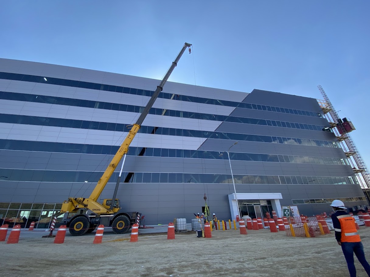
Rigging starts on the drawings: An industrial chiller or air handler can weigh several tons and arrive on site in sections. How it gets in, how it goes up and how it is assembled are decided long before the crane arrives.
Why does rigging start on the drawings?
The day a chiller arrives on site, the whole project comes down to a few hours. There is a crane on hire, a truck waiting and a piece of equipment that represents a large share of the investment hanging from a set of slings.
At that point, almost nothing can be corrected. If the door is narrower than the unit, if the slab cannot support the crane or if a power line crosses the lift path, the problem is not solved on site. It is solved with another date, another crane or demolition.
That is why rigging is planned during engineering. The weight, the dimensions, the access route and the final location are known as soon as the equipment is selected. What remains is turning that data into a plan.
What is rigging and what is field assembly?
On a job site, rigging covers every movement of a unit from the truck to its base: unloading, moving, lifting and setting.
Field assembly comes next. Many large units arrive in sections that are joined on site. They are then leveled, isolated from vibration and made ready for connection.
Both stages matter most for applied equipment. These are units the manufacturer configures for a specific project, such as industrial air handlers and large-capacity chillers. Because of their size, they rarely fit in a single piece or a simple lift.
Why do large units arrive in sections?
The first constraint is not on site, but on the highway.
In Mexico, NOM-012-SCT-2-2017 sets the maximum dimensions for vehicles on federal roads. The maximum width is 2.60 meters, not counting mirrors. The maximum height is 4.25 meters, including the load.
An object that exceeds those limits and cannot be divided falls into a different category. Its transport is governed by NOM-040-SCT-2-2012 and requires a special permit from the Ministry of Infrastructure, Communications and Transportation. That adds paperwork, cost and travel restrictions.
That is why manufacturers split large air handlers into sections that fit on a trailer. Each section travels separately and is joined on site according to the manufacturer’s drawings.
We have seen it in automotive plants. At Ford’s transmission plant in Irapuato, we handled the rigging and installation of 14 TMI air handlers of six sections each, totaling 1,680,000 CFM. For the General Motors expansion in Silao, we mounted, assembled and started up 16 TMI air handlers of four sections each, totaling 522,000 CFM.
What should be checked before the equipment arrives?
A good plan answers simple questions before anyone has to ask them on site.
· Weight and center of gravity. Taken from the manufacturer’s drawings for the selected model, not from a general catalog. The weight that matters is the unit plus the rigging.
· Access route. Doors, corridors, ramps and turning radii, from the street to the equipment base. If the unit does not fit in one piece, decide now whether it ships in sections or an opening must be left.
· Structural capacity. A slab, roof or mezzanine must carry the unit in operation, with water, oil and refrigerant. It must also carry the unit as it is moved into place. That review belongs to the structural engineer.
· Crane position. Where it sets up, how firm the ground is under its outriggers and how far away the load will be. A crane’s capacity drops as the load moves farther out.
· Interferences. Structures, other equipment and power lines along the load path.
· Service clearance. The unit must keep the space the manufacturer requires to operate it, maintain it and, one day, remove it.
The last point is the one most often forgotten. A chiller that went in before the walls were closed can end up trapped. The day it has to be replaced, the rigging will cost far more.
What does Mexican regulation require for crane lifts?
NOM-006-STPS-2023 regulates material handling with machinery in the workplace. It was published in the Diario Oficial de la Federación on March 7, 2024 and replaced the 2014 version. For crane use, these points stand out:
· Written procedures. For installing, operating and inspecting the machinery, based on the manufacturer’s manuals.
· Ground and clearances. Check the stability and bearing capacity of the ground where the crane will stand. Keep minimum distances from energized power lines: 3.04 meters for lines up to 50 kV, and more as voltage increases.
· Trained and authorized personnel. Only someone trained and authorized may operate the crane.
· Signals and communication. A signal code between the operator and the signal person. The signal person stands where the whole path is visible, and the operator does not move the load until the signal is understood.
· Secured load, kept away from people. The load is secured before lifting and, where possible, does not pass over areas with workers or vehicles. If it is hard to handle, it is controlled with tag lines, especially in wind.
· Stop criteria. The standard requires defining when a lift is suspended: rain, strong winds, poor lighting, earthquakes or damage to cables and slings, among others.
If the unit goes on a roof, NOM-009-STPS-2011 on work at height also applies.
What is a lift plan?
It is the document that turns everything above into a sequence. The most widely used international reference is ASME P30.1, Planning for Load Handling Activities, from the American Society of Mechanical Engineers.
The standard distinguishes two kinds of plan. A standard lift plan covers routine lifts. A critical lift plan is reserved for lifts with more risk or complexity: loads near the crane’s limit, tight spaces, operating facilities nearby or a high cost if something goes wrong. The planner decides which category each lift falls into.
A lift plan usually includes:
· The total weight of the load, including rigging.
· The crane, its position, the working radius and its capacity at that radius.
· The rigging: slings, shackles and spreader beams, with their rated capacity marked.
· The lifting points specified by the manufacturer.
· The area to be cordoned off and who gives the signals.
· The weather conditions under which work stops.
Before the load moves, everyone involved reviews the plan in a pre-lift meeting. ASME P30.1 itself includes that meeting as part of the process.
How is a chiller lifted?
Every manufacturer publishes lifting instructions for its equipment, and those instructions govern. The differences between models are significant.
One example is the installation manuals for Trane centrifugal chillers. They call for lifting the chiller horizontally, with a lifting beam and from the lifting points marked on the unit. They warn that the cables may need different lengths so the load rises level. Some models must not be moved with a forklift.
The lifting beam keeps the cables vertical. That prevents them from pressing on the sides of the unit, where piping, panels and instruments are not built to carry weight.
For the buyer, the takeaway is practical: request the installation manual for the exact model before planning the lift, not after.
What happens once the unit is in place?
Field assembly is the least visible stage and the one that most determines how the equipment will perform.
· Sections in order. Each section of an air handler has a set position. Before joining them, the manufacturer’s drawings and tags are checked.
· Sealed joints. The sections are drawn together, bolted and the gasket between them is compressed. If the gasket is not compressed, air leaks through the joint.
· Leveling. Each manufacturer sets its own tolerance, and it varies by model. For some centrifugal chillers, Trane requires a maximum difference of 1.6 millimeters along the length and width of the unit. An air handler that is out of level does not drain its condensate pan properly.
· Base and vibration isolation. The base must carry the operating weight. Isolators, neoprene or spring, keep vibration from reaching the structure. The ASHRAE Handbook—HVAC Applications devotes a chapter to noise and vibration control.
· Independently supported piping. Piping carries its own weight. The unit should not support it.
Then come the connections, testing and balancing. A poor assembly shows up there: as an air leak, vibration or an airflow that does not reach its design value.
What should be defined during engineering?
These decisions are better closed at the desk than on site:
· Weight and dimensions. Per section, taken from the manual of the selected model.
· Shipping method. Whether the unit travels whole or in sections, and whether a special transport permit will be needed.
· Full route. From the street to the base, with any openings that must be left.
· Structural review. Of slabs, roofs and bases, using the operating weight.
· Space for the crane. Where it will stand and what it will rest on.
· Lift date. Tied to the actual delivery date of the equipment.
The last point connects to another topic. Large units can take months to manufacture. If the delivery date moves, the lift is rescheduled with everything that implies: crane, permits and crew.
What you see on site was decided earlier
A good lift looks calm. The crane arrives at the planned spot, the unit passes where it was planned to pass and rises where it was calculated to rise. What happens that day is the result of decisions made weeks before.
At Reaclima we design, supply and install industrial HVAC systems, and the rigging and field assembly of applied equipment are part of that scope. We then test, balance and start up what we install.
If your next project includes large equipment, let’s talk.


